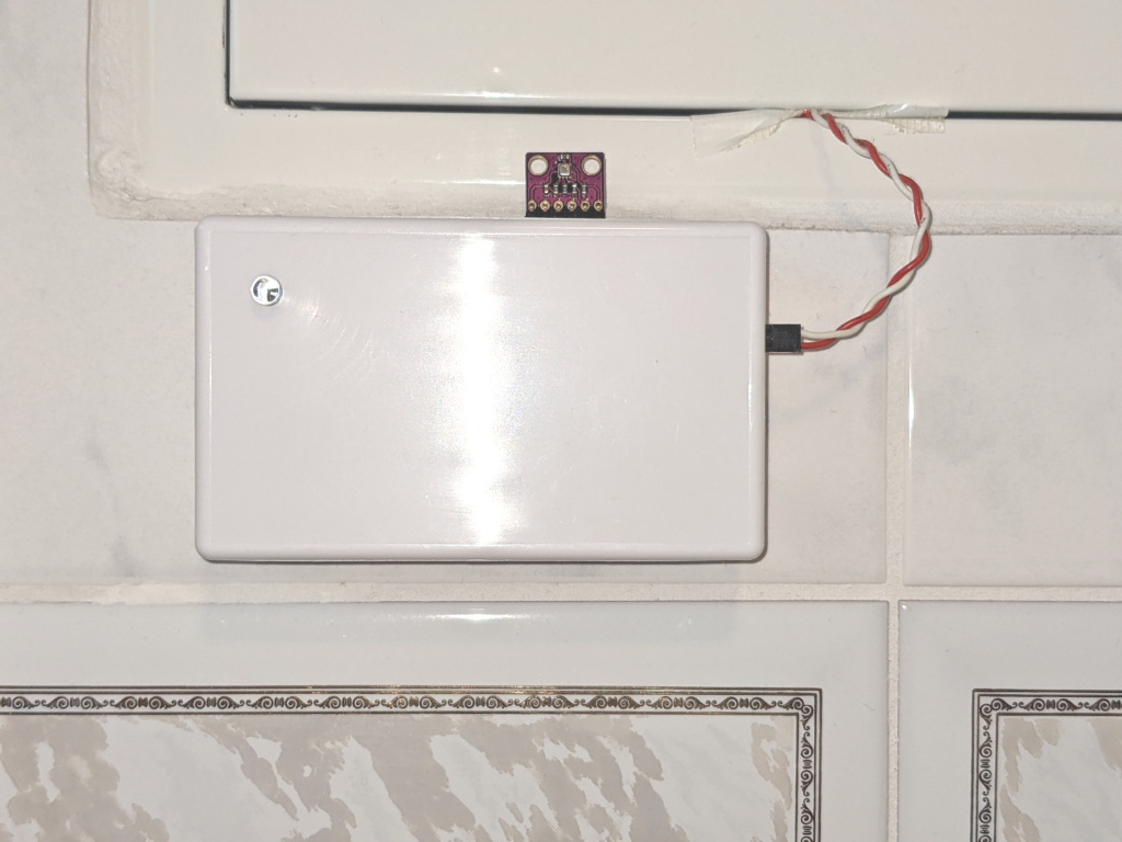
This sensor node is attached to the gas meter in my home. It uses a 2,4 GHz RF link to a MySensors MQTT gateway to reports natural gas consumption data to my home automation controller. The gas meter is of the type that creates magnetic pulses when the meter dial moves, so the connection is contact-less, and works without access to the inside of the “official” meter from the utility company.
This is part of my home automation setup, for more details see the previous posts.
In this blog post, I will state my objectives for this project, describe the hardware, software and openHAB integration, and then revisit my objectives and see to what extent I have achieved what I had set out to do.
All of the sensor code and hardware schematics are available in Github.
Objectives
My main objectives for this project were
- I want to know the cost of heating, i.e. natural gas consumption, throughout the year.
- I expect this to be a low-cost, low-hassle system, i.e. low cost of materials, and infrequent battery changes.
- I expect the system to work in “sunny day operation” (pardon the pun) as well as in edge cases, i.e. restarts of the sensor, or restarts of the home automation system, or temporary failure of the gateway.
Features
- The sensor node interfaces with a gas meter the generates magnetic pulses proportional to the amount of gas consumed.
- The sensor node interfaces with the MySensors network of low-power RF nodes.
- The sensor node reports information via MQTT, via a MySensors-to-MQTT gateway. This information can be interpreted by openHAB, and probably also other home automation controllers.
- Optionally, the node can also read an ambient brightness sensor and a climate sensor (temperature, atmospheric pressure, humidity) and report those at regular intervals. I found this useful because our gas meter is located inside the bathroom.
Software
Incremental vs absolute measurements
Initially, MyGasMeter only reports incremental data:
- frequently, it reports the incremental pulse count since the last report.
- once per hour, it reports flow [liters/hour] calculated from pulse count.
Once it has received a base count value from the controller (see below), it also starts reporting absolute data:
- frequently, it reports the absolute pulse count, i.e. base value + pulses since power on.
- once per hour, it reports total gas volume [liters] consumed, i.e. (base value + pulses since power on) * liters/pulse.
With this two-stage approach, the node will always report correct absolute pulse count, even if the gateway misses a message now and then. Also, you can replace the battery on the node and then re-initialize it for the correct absolute pulse count, without relying on EEPROM memory.
The liters/pulse conversion is a constant in the source code which you may have to change, depending on your particular gas meter.
Optionally, the node can also read an ambient brightness sensor and a climate sensor (temperature, atmospheric pressure, humidity) and report those at regular intervals. I found this useful because our gas meter is located inside the bathroom.
Hardware
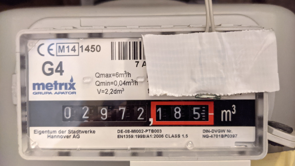
The gas meter in our home is a G4 Metrix 6G4L. It has a display of 8 “mechanical” digits, showing cumulative gas consumption in liters. For every rotation of the least significant wheel it generates one magnetic pulse, i.e. one pulse for every 0.01 m³ of gas consumed. I guess there is a small permanent magnet attached to that wheel.
The magnetic pulse is sensed with a reed switch attached to an ATmega328 based MySensors node. I use a KSK 1A87 from Reichelt. I learned about the correct placement of the reed switch from this picture .
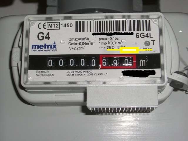
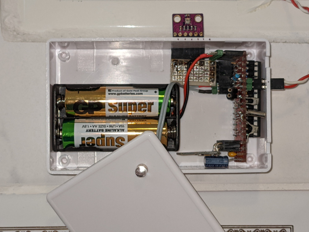
The MySensors node is built from a My Slim 2AA Battery Node, with a 32,768 Hz watch crystal attached to XTAL1 and XTAL2 (see hardware folder in Github for schematic).
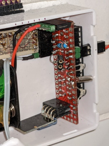
Our house has two gas furnaces (don’t ask why …), so I built two of these sensor nodes. One is just the gas meter sensor, in a piece of white cable duct as a case, the other has the additional ambient brightness and climate sensors, and fits in a simple 100x60mm plastic project box from Aliexpress.
In one unit, I needed to attach the NRF24 module to the bottom of the “slim node” PCB, so I used the SMD version of the module, with wires soldered to look like a mirror image of the regular NRF24 module.
The node is powered by 2 AA batteries; the last set of batteries lasted for about 20 months without and 12 months with brightness and climate sensors.
The I/O connections are very simple:
- the reed switch is attached to PD3 and PD4,
- an optional photo transistor is attached between PC2 and GND, and via a 100 kΩ resistor to PC3, so it can be powered only when needed.
- an optional BME280 climate sensor is connected to the I2C interface on PC4, PC5.
- an LED can be temporarily attached between PC0 and GND via a 1 kΩ current limiting resistor. This helps with finding the correct spot for the reed switch, see below.
- for debugging purposes, PC1 goes HIGH whenever the controller is not sleeping.
Installation
Before installing the sensor, I attached an LED and 1 kΩ resistor to pin PC0 of the microcontroller. The software mirrors the state of the reed switch on the LED. Then I cranked up the heat, so the gas meter dial was turning, and I positioned the reed switch over the least significant digit of the meter until the LED flashed once per revolution of the dial. After fixing the reed switch with tape, I removed the LED.
Initialization
After power up (e.g. after you put in a fresh battery), the node will
- present its sensor items (sensors) as expected by the MySensors framework.
- request from the gateway a base value for absolute pulse count (sensor 81, type V_VAR1),
- report an absolute pulse count (sensor 81, type V_VAR1) of zero
The node will not sleep until a base value for absolute pulse count has been received, so don’t wait too long to provide this value, to conserve battery. It will continue to request a base count value at regular intervals until it receives an answer.
The following description is based on my setup, you need to adjust for your setup:
- The sensor is node #126
- There is a MySensors MQTT gateway that publishes messages from the sensor as topic my/+/stat/126/# , and forwards messages with topic my/cmnd/126/# to the sensor
- mosquitto is used as the MQTT broker,
Set base count via MQTT command line
To set the base count value via MQTT, follow these steps. A more elegant, automated way to do this with openHAB is described below.
- in one shell listen to messages from that node
mosquitto_sub -t 'my/+/stat/126/#'- wait for the sensor to send its initial report, e.g.
my/2/stat/126/81/1/0/24 0
my/2/stat/126/81/2/0/24- then, in another shell, set the initial value (gas meter showed 6591.970 m³)
mosquitto_pub -t "my/cmnd/126/81/1/0/24" -m '659197'openHAB integration
I use openHAB for home automation, currently version 2.4, but other environments should work, too.
Items
openHAB items are defined for each sensor type reported by the node. I am still using the MQTT v1 binding.
// relative pulse count reported by node, since last report
Number GasMeter_L_RelCount "Gas Rel Count L [+%d]" <gas>
   {mqtt="<[mosquitto:my/+/stat/126/81/1/0/25:state:default]"}
// absolute pulse count reported by node, or 0 if base value has not been received yet
Number GasMeter_L_Count "Gas Count L [%d]"         <gas>
   {mqtt="<[mosquitto:my/+/stat/126/81/1/0/24:state:default]"}
// absolute pulse count used in OpenHAB, persistent, sent back to node on request
Number GasMeter_L_AbsCount "Gas Abs Count L [%d]"  <gas>
// liters per hour as reported by node
Number GasMeter_L_Flow "Gas Flow L [%d l/h]"       <gas>
   {mqtt="<[mosquitto:my/+/stat/126/81/1/0/34:state:default]"}
// total gas volume in liters displayed by gas meter
Number GasMeter_L_Volume "Gas Vol L [%d l]"        <gas>
   {mqtt="<[mosquitto:my/+/stat/126/81/1/0/35:state:default]"}
One unbound item stores absolute pulse count
Number GasMeter_L_AbsCount "Gas Abs Count L [%d]"  <gas>
// liters per hour as reported by node
Two items represent the request for an absolute count value sent by the node, and the response
String GasMeter_L_VAR1_Request
   {mqtt="<[mosquitto:my/+/stat/126/81/2/0/24:state:default]"}
Number GasMeter_L_VAR1_Response
   {mqtt=">[mosquitto:my/cmnd/126/81/1/0/24:command:*:default]"}
If the code is compiled with support for the optional brightness and climate sensors, then those are converted to openHAB items as well
Number BRL_Lux          "Brightness [%.0f%%]"      <slider>
   {mqtt="<[mosquitto:my/+/stat/126/61/1/0/23:state:default]"}
Number BRL_Temp         "Temperature [%.1f°]"      <temperature>
   {mqtt="<[mosquitto:my/+/stat/126/41/1/0/0:state:default]"}
Number BRL_Hum          "Humidity [%.0f%%]"        <humidity>
   {mqtt="<[mosquitto:my/+/stat/126/51/1/0/1:state:default]"}
Like all my sensor nodes, it reports its own battery voltage, in absolute millivolts and as a percentage of usable battery voltage range
Number GasMeter_L_VCC   "Gas L VCC [%.0f mV]"      <gas>
   {mqtt="<[mosquitto:my/+/stat/126/99/1/0/38:state:default]"}
Number GasMeter_L_Bat   "Gas L Bat [%.0f %%]"      <battery>
   {mqtt="<[mosquitto:my/+/stat/1
Set base count via openHAB REST interface and rule
Before you power up the node for the first time, go read the current gas volume displayed by the gas meter, and set the corresponding openHAB item e.g. via the REST interface.
Say the meter shows 6591,970 m³, and your openHAB item is named GasMeter_AbsCount . Enter on the command line
curl -X PUT --header "Content-Type: text/plain" --header "Accept: application/json" -d "659197" "http://servername:8080/rest/items/GasMeter_AbsCount/state"or use the interactive REST interface at http://servername:8080/doc/index.html .
Rules
Two simple openHAB rules are defined for the gas meter.
Rule 1: if node reports an absolute pulse count > 0, then trust it and write it to the unbound item used within openHAB.
rule "update gas meter click"
when
    Item GasMeter_L_Count changed
then
    var newCount = GasMeter_L_Count.state as Number
    if (newCount == NULL) newCount = 0
    if (newCount > 0) {
        GasMeter_L_AbsCount.sendCommand(newCount)
    }
end
Rule 2: when the node requests an absolute base value, reply with the absolute pulse count used by openHAB.
rule "send init val to gas meter"
when
    Item GasMeter_L_VAR1_Request received update
then
    GasMeter_L_VAR1_Response.sendCommand(GasMeter_L_AbsCount.state as Number)
end
Implementation notes
If you just want to use this gas meter node in your home, then ignore the rest of this section. If you want to learn from this for your own projects, then read on …
Watch crystal instead of sleep() function
The node must be battery-powered (read: low supply current, sleep as much as possible), but it can’t use the MySensors sleep() function, because we need a fairly accurate timebase so we can report flow in liters per hour.
We use the (not so accurate) internal RC oscillator of the AVR to clock the CPU, but a (much more accurate) external 32768 Hz crystal to clock Timer2, which generates interrupts every 10ms, so we can debounce the reed switch, and do all other housekeeping as needed.
In between interrupts, we sleep in SLEEP_MODE_PWR_SAVE mode, which stops most of the processor’s peripherals, except for Timer2. During sleep, Timer0 as used by the Arduino framework is stopped, so we can’t rely on the Arduino millis() function for timing. Instead, we use a milliseconds counter incremented by the Timer2 ISR for timing purposes (has an hour passed? should we report pulse count or flow or climate?).
Delayed climate sensor readout
According to the BME280 datasheet, one measurement of temperature, humidity and pressure takes >11ms. The normal measurement function from the Arduino library will request a measurement, wait until it is completed, and then read out and return the measurement results.
A more power-efficient way to do this is to request a measurement just before sending the processor to sleep, and then read out the measurement results 1s later, the next time the loop() function is run.
More power saving
The pin sensing reed switch closure is programmed as a input with the internal pull-up resistor enabled. The goal here is to avoid a situation where current would flow through the pull-up resistor as long as the magnetic pulse is active — which could be a long time if the meter happens to stop in the position of the display dial where the magnetic signal is active.
To avoid that, the other end of the reed switch is not connected to GND, but to another AVR pin programmed as an output. Most of the time, that other AVR pin is set to HIGH. When the switch needs to polled, the pin is briefly set to LOW, and the signal is read.
With this setup, the average power consumption is about 50µA at 3.3V with an 8 MHz processor clock and a ~100 Hz interrupt rate.
Accuracy
The very attentive reader will now ask: how can you achieve an interrupt rate of exactly 100 Hz with a 32768 Hz timer clock frequency, using the AVR timer capabilities? Answer: you can’t, the interrupt rate is 99 Hz, so the reported flow in liters/hour is off by 1%, and the specified timing of “report once per hour” or “report once per 5 minutes” is also off by 1% … acceptable for my use cases. Note that the reported absolute pulse counts are always correct, so if you calculate m³/day from those, it will be correct.
Mission accomplished?
So, did I meet the objectives I stated at the beginning?
- I want to know the cost of heating, i.e. natural gas consumption, throughout the year: Yes. I now have a better understanding of how much I spend on gas, month by month.
- I expect this to be a low-cost, low-hassle system, i.e. low cost of materials, and infrequent battery changes: Yes, with a material cost under 5 EUR (for the small version without climate sensor), and battery life of more than 12 months, good enough
- I expect the system to work in “sunny day operation” as well as in edge cases: Yes. With the system of incremental and absolute counts described above, the design can handle restarts of the sensor as well as restarts of the home automation system.
Acknowledgements
The reed switch solution was inspired by this blog post: https://www.energiesparhaus.at/forum-gaszaehler-metrix-6g4l-reed-kontakt/29038 (in German).